Rule Generators
The L1S Generator
With the base object set up, we’re ready to create the recipe that tells RailClone how to assemble the model. To do this we need a rules Generator. The L1S, or linear generator is the simplest of the two found in RailClone, but don’t let that fool you, it’s enormously powerful! It has Six inputs named start, end, corner, evenly, marker and default that all simply identify different positions along the base spline on which geometry can be placed. Creating a parametric object is as simple as attaching the geometry to each of these inputs.
To illustrate, here’s how we’d recreate our bus shelter.
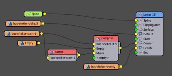
- Wire the Spline node to the Generator’s Spline input.
- Wire the bus-shelter-start-1 Segment to the generator’s Start input. Geometry will appear at the beginning of the spline.
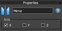
- Wire the same segment to the End input and it appears at the end of the spline, but of course, it is oriented incorrectly. To fix this we use a Mirror operator which gives you the option to flip geometry on the X,Y and/or Z axes.
- Now wire the bus-shelter-default-1 segment to the Default input. This input is used to fill in between all the others with geometry. In this case, it is adding the roof and glazing between the start and end. If you edit the length of the spline you will see you already have a working parametric model. Easy as that!
- The way in which Default geometry is distributed along the spline is controlled using the Generator’s Default Mode setting. By default, it simply tiles one piece after another until it reaches the end of the spline where any excess is simply sliced off. Other options include Count which allows you to set a specific number of times the geometry is repeated, Adaptive which is like tile except that is subtle rescales the geometry to ensure no slicing is required, and finally Scale which stretches one complete segment in between the other inputs. That’s the mode we’ll use for this object.

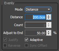
- Now let’s add the struts. Wire the bus-shelter-evenly segment to the Evenly input. The geometry in this input is repeated at regularly spaced intervals along the path. To control the distance, you select the Generator and go to the Rules > Evenly settings. Similar to the Default segment’s settings, you have options to decide if the Evenly divisions are based on distance or a fixed count. If you choose distance you can control the spacing, including how the spline is divided at the start and end using the Justify and Adaptive options. You now have a fully parametric version of the stock model with an adjustable size, and strut spacing.
- But what about corners? Corners allow you to place geometry on specific types of vertex which are nominated using the Generator’s Rules > Corner > Vertex type settings.
- If you leave the settings at their default you will see that the Default segments are neatly bevelled around the corner.
- Let’s add a gap on the corners instead. To do that we will need to finish the shelter just before the corner, and start the shelter again after the corner. We already have the geometry to do this, but it is output from two different nodes, and we have only one input on the generator. That’s where the Compose operator comes in. It allows you to glue several segments together and add them to a single input.
- To use it, wire a Compose node to the Corner input. Wire the output of the Mirror node to the first input and the bus-shelter-start-1 segment to the second input. So far so good, but how to create the space between them? You do this with what we call an Empty segment. This is simple a segment node in which no geometry has been selected and it’s incredibly useful for adding spaces to your object. To illustrate, wire a new Segment node to the Compose operator and use the Up/Down arrows to move the input so that it is second in the list. Because it is the 2nd of 3 inputs it will be centred on the corner vertex.
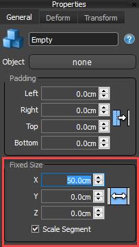
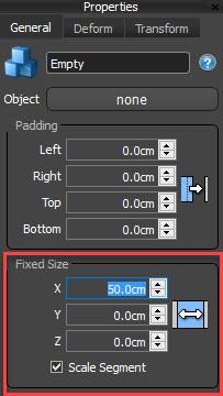
- Now you can use this segment to add a gap on the corners by simply selecting the node and increasing the Fixed Size setting found in its properties. As you increase the value the two other segments are pushed apart.
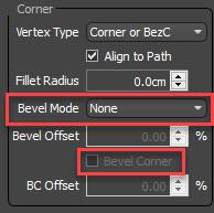
- You might wonder why the roof and glass continue through to the corner. This is because geometry in the Corner input does not interfere with Default geometry unless one of two settings are enabled. Either set the Bevel Mode to None, or enable the option to bevel the geometry that’s wired to the corner input. If either of these options are enabled, the default segment stops when it reached the corner geometry. Which is what we want in this case.
Don’t limit yourself - add as many generators as you need!
When starting out with RailClone, it is tempting to try to cram everything into one Generator, but in fact, it is often much much easier to spread out a style across multiple generators. To demonstrate, we will use a second generator to add the seats.
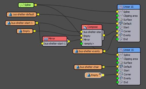
- Add a new L1S Generator to the graph and attach the existing Spline node.
- Add a new Segment node and use it to select the chair geometry from the scene.
- Wire the Segment node to the Default input. Change the mode to Adaptive so that we always have whole chairs.
- If the chair is in the wrong place, tell RailClone to use the pivots we set at the beginning of this tutorial by going to Alignment and set Y and Z properties to pivot.
- Another issue you will see is that the chairs continue to the corner of the spline. To fix this we can use the same empty segment trick. Add a new segment to the Corner input and increase the Fixed Size parameter until the chairs fit neatly inside the shelter.
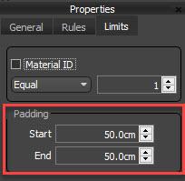
- The same problem is seen at the start and end. To fix it, select the generator and go to the Limits tab. Here you will see Padding settings which allow you to offset the start and end of the path. Increase these values until the chairs no longer intersect the sides of the shelter.
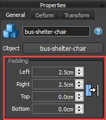
- On the subject of Padding, parameters of the same name can be found the Segment node’s properties. Here they can be used to control the spacing between segments. A positive value pushes segments apart, a negative value causes them to overlap. Here we will add a small positive value to create some space between the seats.
- And that’s the basic style set up. All that remains is to assign the material by picking it from the source object and applying it to the RailClone object.
- If you fancy a challenge - do the same thing to add a digital display to the start of each bus shelter using a new generator.


